
This article goes through the process of estimating altitude and vertical velocity using barometer and accelerometer, blending them togheter and create a control loop to allow the 2″ inches Arduino drone to hover.
the basics: rC input
The radio receiver interprets user commands from the remote controller and communicates them to the flight controller. In hover mode, the throttle stick follows a specialized logic:
- When the stick is positioned within a central deadband range, the drone enters altitude hold mode.
- Outside this range, the throttle behaves normally, allowing the user to ascend or descend.
This configuration ensures smooth transitions between manual control and autonomous altitude holding.
Altitude hold and sensor fusion
The drone maintains level flight and consistent altitude by fusing data from a barometer and an accelerometer. The barometer provides altitude data via air pressure measurements, while the accelerometer, after appropriate processing, yields vertical velocity. A complementary filter merges these data streams to produce reliable and accurate altitude and velocity estimates.
1. Barometer – Altitude Measurement
The objective is to acquire real-time altitude data. The challenges, and my proposed solutions are:
- Slow response: Barometer functions are often blocking and significantly reduce loop frequency (from ~200 Hz to ~50 Hz), making it very hard for a drone to flight properly. A dedicated non-blocking approach was implemented (see separate article) to return to a 200 Hz loop frequency.
- Noise: A double low-pass filter (LPF) was applied to smooth the signal which in its raw format is very noisy. This introduces some delay in recognition in altitude changes, estimated in around ~1 second, depending how strong is the LPF.
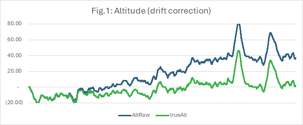
- Drift: Barometer measures tend to drift overtime. This was addressed by detecting and labelling altitude variations below a certain threshold, and integrating them into a variable called driftOffset, which would be deducted from the raw barometer measurements. This system of addressing the problem allows for real time correction and flexibility, as drift can vary greatly between flights. In fig. 1 with drone stationary it can be seen the green line almost completely reduces the drift.
The result is a relatively clean altitude signal, albeit with some latency and residual noise. This is addressed through sensor fusion.
2. Accelerometer – Vertical velocity Estimation
The objective is to derive vertical velocity, and the challenges as well as my solutions are:
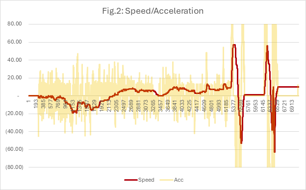
- Signal noise: Sensor-level filtering (setDLPFMode(2)), a secondary LPF, and a deadband threshold help reduce noise. The first two help reduce high frequency noise, while the third low frequency noise and small drift.
- Conversion and orientation: Measurements in g-units are converted to cm/s², gravity is subtracted from the z-axis, and readings are transformed from the local frame to the global frame. This must be done to obtain vertical velocity even when drone is tilted.
The processed signal provides a good estimation of velocity, though it tends to drift over time—particularly when the drone is tilted. In fig. 2 we can see the noise of raw acceleration data in yellow, solved with the techniqques above, and the drift of velocity in red.
3. Complementary Filter – Data Fusion
At this point we have altitude from the barometer and vertical velocity from the accelerometer. The features of these are:
- Barometer/Altitude: Stable but slow
- Accelerometer/Velocity: Fast but prone to drift especially if drone is tilted
A complementary filter blending together the two sensors can improve the final estimation of velocity and altitude.
Velocity Fusion:
- The estimated velocity from the accelerometer is corrected using altitude changes derived from barometer data.
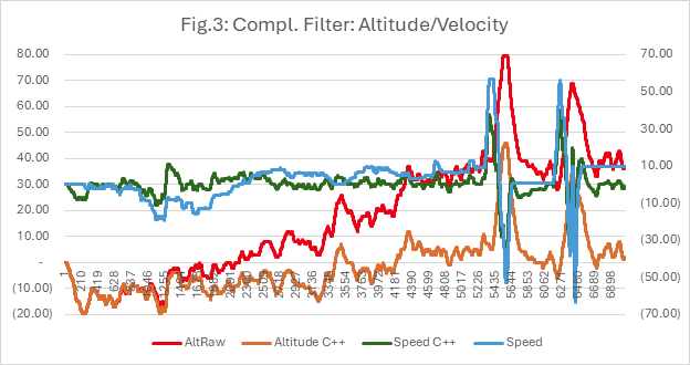
- A blending ratio of 99.8% accelerometer and 0.2% barometer was found effective in eliminating drift while retaining responsiveness.
Altitude Fusion:
- Attempts were made to use velocity to enhance the responsiveness of altitude estimates. However, results were inconclusive due to increased noise and feedback loop interference. Further refinement may yield improved performance.
The results are encouraging as can be seen in fig.3 below. In orange the altitude before drift correction and complementary filter, and in red the corrected altitude, measured on the scale on the left. In blue the velocity before complementary filter and in green after, as can be seen drift is removed. Velocity refers to scale on the right.
4. Control Loop for Altitude Maintenance
The system works around two nested control loops:
- Outer loop: Compares desired altitude with current altitude and outputs the required vertical velocity. The desired altitude is read once the drone enters hovering mode (RC stick is centered).
- Inner loop: Compares desired velocity with current velocity and generates motor control outputs.
Output limits are applied to both loops to prevent aggressive ascent or descent and mitigate the impact of sensor noise.
Results & Resources
This layered approach ensures smooth and reliable altitude control.
Fusing data from a barometer and accelerometer allows for stable altitude and velocity estimation, even in a highly compact drone. Despite the inherent limitations of each sensor, the use of filtering and control logic results in reliable hover performance.
- My Code Implementation (full drone program) – download
- Video Tutorial (Using barometer for altitude hold) – Video link
- Altitude data fusion utilising differential measurement and complementary filter, by Wei, Dan and Chen, 2016.
Leave a Reply