
Portfolio – Arduino 2″ Drone

Project intro
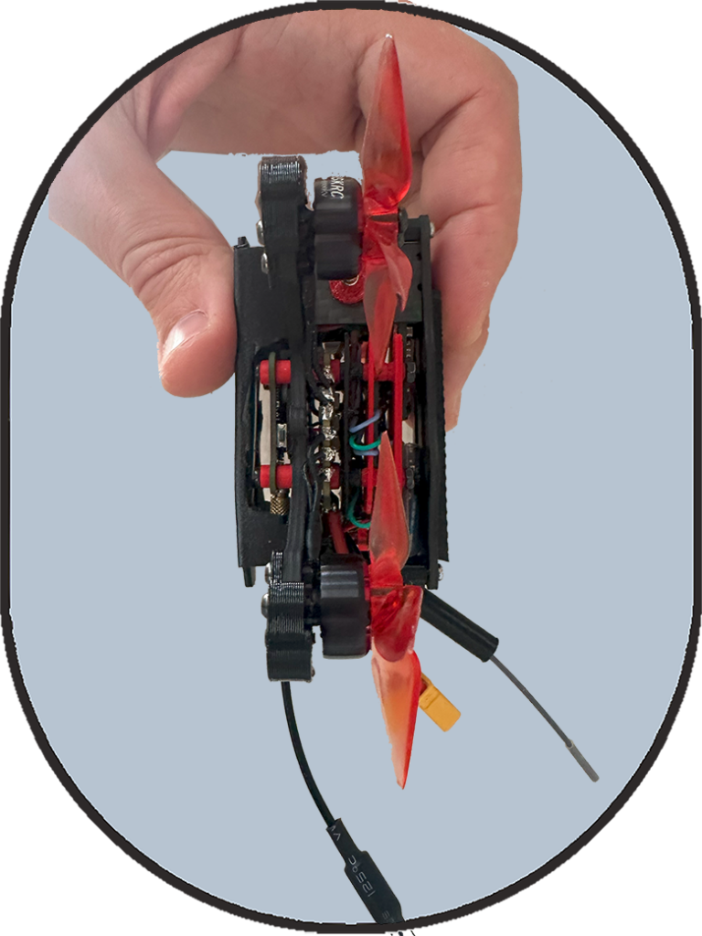
This is my second Arduino-based drone, a compact 2-inch build that improves upon my first design with both enhanced features and a more efficient layout. While this version introduces richer functionalities, its smaller size has also presented significant challenges, requiring careful planning in component selection and placement to optimize space. This drone offers three flight modes:
1. Acro Mode (Speed-Controlled) – The drone’s rotational speed is managed using the gyroscope. By comparing its measured velocity along the three axes with the RC controller inputs, the system adjusts motor power to achieve the desired movement.
2. Angle Mode (Angle-Controlled) – This mode calculates the drone’s tilt using a combination of gyroscope and accelerometer data. The motors are then adjusted to maintain the desired orientation, making it easier to control.
3. Horizon Mode (Altitude-Stabilized) – This mode introduces altitude hold, achieved through sensor fusion between the accelerometer and barometer. It helps the drone maintain a stable height with minimal manual input, improving flight control and stability.
Beyond flight control, this drone includes a beeper for audio alerts, and a battery voltage monitoring system using a resistive network, ensuring safe operation by preventing over-discharge.
By balancing advanced features with the constraints of a smaller frame, this build demonstrates the importance of precise component selection, space optimization, and system integration in micro drone design.
Key Concepts
To fully understand and optimize this 2-inch Arduino drone, here are some key concepts and tools that play a crucial role in its performance:
How Gyroscopes, Accelerometers, and Barometers Work – Gyroscopes measure angular velocity, helping the drone detect rotational movements. Accelerometers measure linear acceleration and are crucial for determining tilt and orientation. Barometers measure air pressure, allowing the drone to estimate altitude by detecting pressure changes. Watch this explainer video for a deeper dive into how these sensors work.
Filtering Noisy Measurements – Sensor data is often noisy and unreliable without proper filtering. This drone applies different techniques to improve accuracy:
- High-Pass Filter or Dead Bands – Removes slow-changing biases, ensuring cleaner motion detection.
- Low-Pass Filter – Helps smooth out sudden random fluctuations, providing more stable measurements.
The Importance of Sensor Fusion for Altitude Control – No single sensor is perfect, even after filtering, but combining data from multiple sensors improves accuracy. By fusing accelerometer and barometer readings, the drone can have good enough estimates for altitude and vertical speed to allow altitude hold of a drone possible.
PID Control Loop – The Core of Flight Stability – The Proportional-Integral-Derivative (PID) control loop is at the heart of how the drone maintains stability and responds to commands. It continuously adjusts motor power based on sensor feedback to correct errors in:
- Angular velocity (Acro Mode) – Ensures smooth and precise rotations.
- Tilt angle (Angle Mode) – Helps keep the drone level.
- Altitude (Horizon Mode) – Maintains a steady height by processing barometer and accelerometer data.
Fine-tuning PID values is crucial to achieving a stable and responsive flight.
By mastering these principles, you can fine-tune flight stability, altitude control, and overall drone performance, pushing the limits of Arduino-based drones. Check last section in this page for deep-dives on these topics.
Components
APEX 2 frame
MPU6050-GY86 with gyro, accelerometer, barometer and magnetometer
Arduino Nano Board as flight controller
4-in-1 ESCs and PDB
Camera and VTX
4 Brushless Motors

Sources & extras:
The original code can be found on GitHub.
The modified code for this project can be downloaded here.
For a deep-dive on filtering sensors raw data and combining them to get reliable velocity and altitude check my post here.
For a deep-dive on implementing a non-blocking function to read barometer data while keeping the drone 250 hz loop time click here.
For a summary pdf where I highlighted the major modification I made to the code and some challenges I faced click here.
For the electronic circuit schematics click here.
For the 3d printed parts click here.